LRTimelapse timer free Max
Here’s my assembly guide for LRTimelapse timer free Max an intervalometer on steroids. Where to get one. Contact Hans/Sheeba at forum.lrtimelapse.com
Hardware versions
There are several versions of
- LRTimelapse Pro Timer 3 and 2.5 11 , from the developer of LRTimelapse software, Gunther Wegner, this a commercial fully working unit, just buy the cable for your camera and off you go. Skip the rest of the article :p
- The Open Source free timer LRTimelapse timer free , also from Gunther, based on Arduino Uno and common LCD/button shield, source code
- LRTimelapse Pro Timer free Max, based on MEGA 2560 mini and common LCD/button shield. 1 . Using the free timer as the base, Hans started adding lots of features, hence the upgraded Arduino.
- LRTimelapse Pro Timer free Max/Mega 2, using MEGA 2560 mini and TFT display configured in landscape layout.
- LRTimelapse Pro Timer free Mega 3, using MEGA 2560 mini and TFT display configured in portrait layout.
Parts
When purchasing the kit, you also have several options to take, buy a fully assembled working kit, or buy only what you need which is the one I took. So that I could buy two sets and source the other parts locally.
Here’s the content of the kit per set that I bought
- 1 pc x Carrier board v1.3
- 2 pcs x 3.5mm TRS socket
- 1 pc x Single Pole Double Throw (SPDT) Switch
- 1 pc x TP5100 Battery charger, already configured for 8.4V
- 1 lot x 1-row 2.54mm female headers for LCD display
- 1 lot x 2-row 2.54mm male headers for Mega
- 1 pc x fiber optic light guide
- Housing and 3D printed buttons
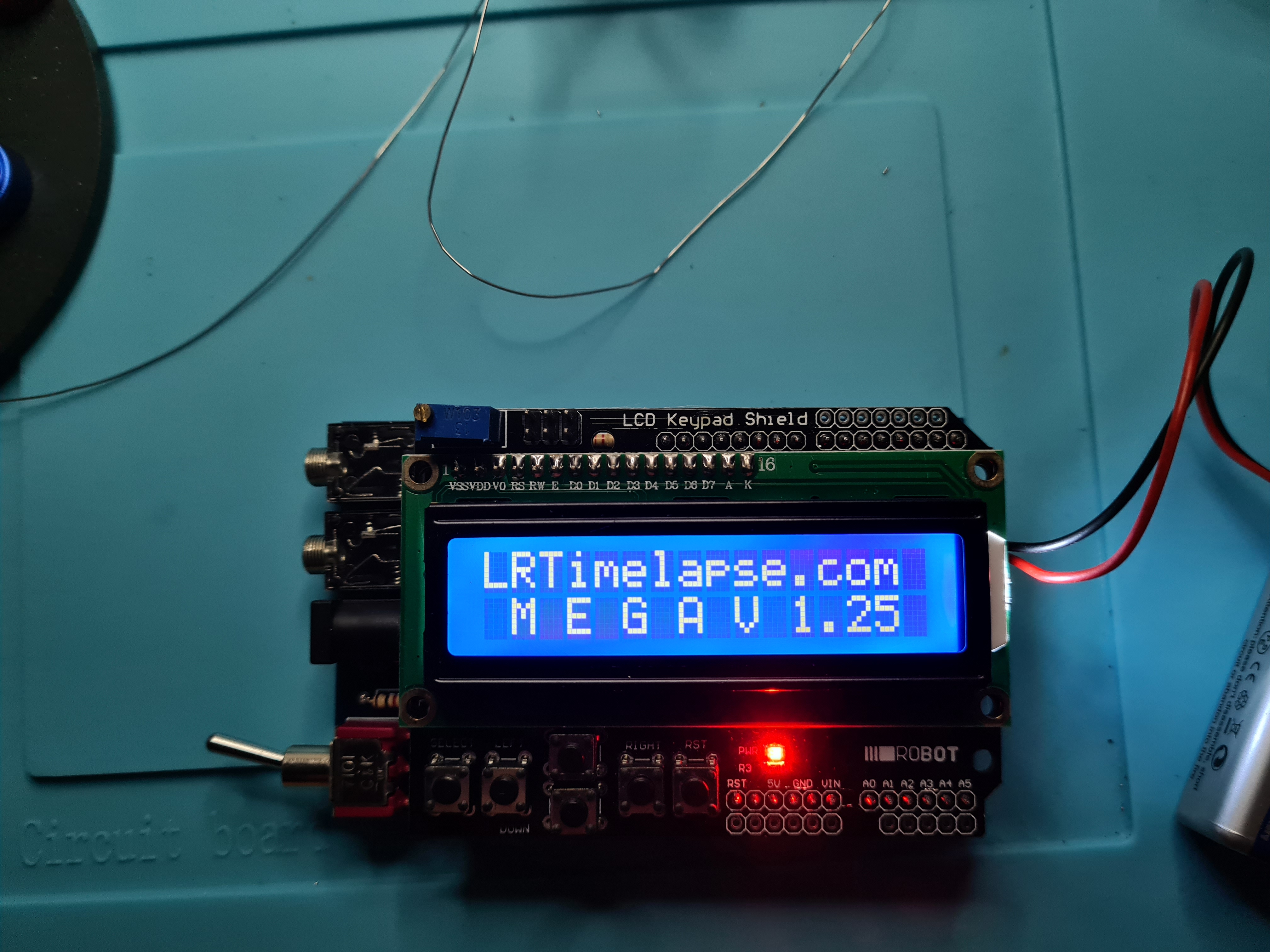
Also included in thru email are some instructions on soldering the components, compiled firmware(v1.25 at that time), and how to upload it to Arduino using Xloader(Windows).
These are the parts I sourced locally here in the Philippines.
- 1 unit x Arduino Mega 2560 Pro Mini
- 1 pc x 5V to 12V DC-DC converter
- 1 pc x LCD button shield
- 2 pcs x BC547 General Purpose NPN Transistor
- 1 pc x 2N4403 (BC557B)
- 2 pcs x 4.7k ohm resistor
- 2 pcs x 10k ohm resistor
- 2 pcs x 1k ohm resistor
- 1 pc x 200k ohm resistor
- 1 pc x 3.9k ohm resistor
- 1 pc x 2.2k ohm resistor
- 1 pc x 9V battery
- 1 pc x 1N5819 Schottky barrier rectifier diode (BAT48)
- 1 pc x 220uF 16V electrolytic capacitor
- 1 pc x 1uF 16V electrolytic capacitor
- 1 pc x DC Socket, PCB mounted
- 1 pc x EBL 9V 6F22 600mAh Lithium-ion Rechargeable
Assembly
Assembly is started by soldering the following components into the carrier board
- resistors and diode
- capacitors and transistors
- female headers
- SPDT switch, DC socket, and TRS socket
- TP5100, you’ll need to use excess wires from the resistor to solder this to the carrier board
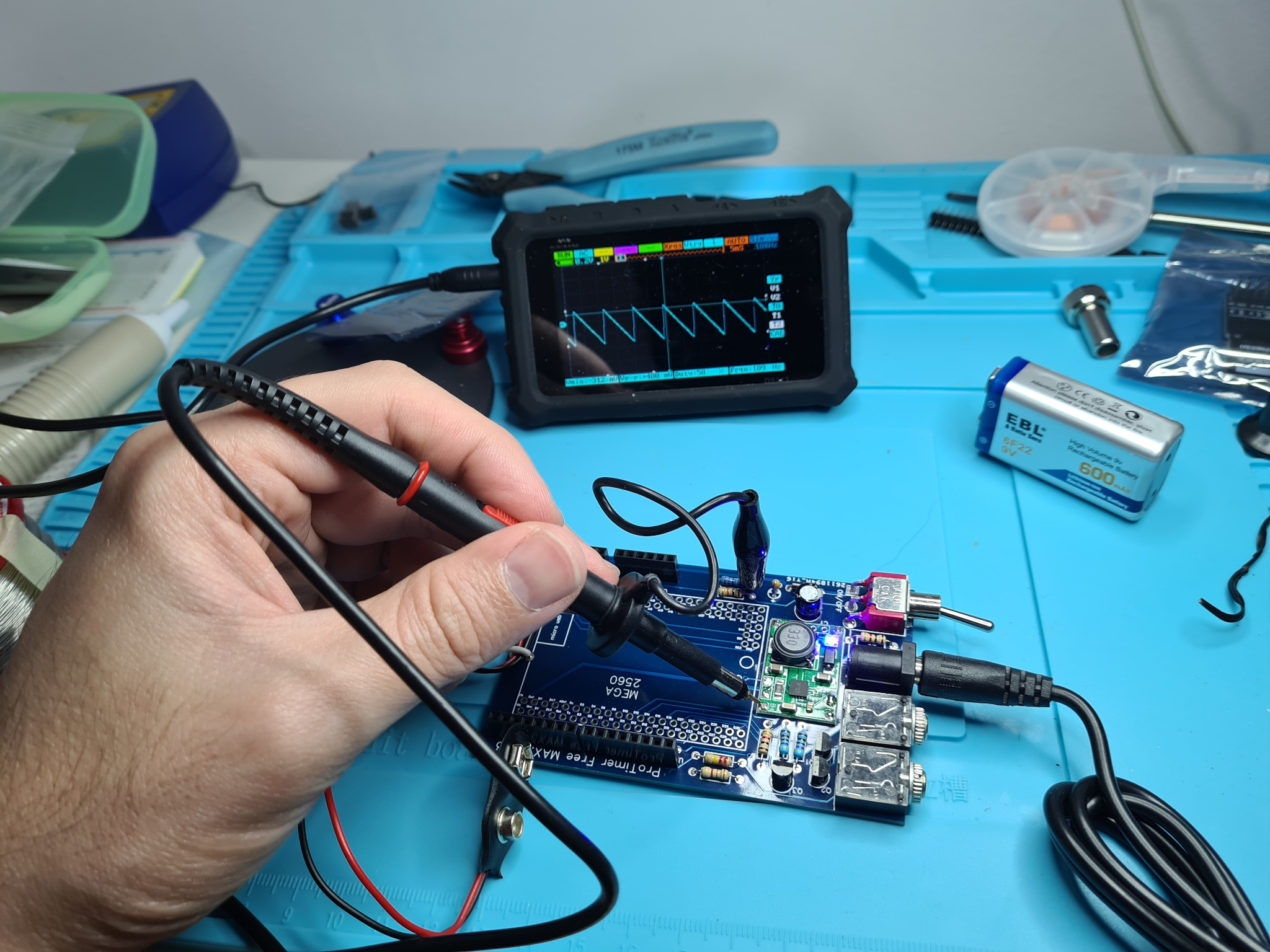
Once this is done. It would be good at this point to inspect if there are possible shorts and cold solder. I also did some testing on the TP5100 to make sure it working as expected
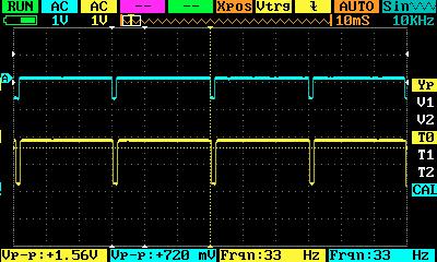
Without the 9V battery apply 12V via the DC socket. Both the CHG and STDY LED should light up and flash. But since those LED’s are quite bright it would be hard to see them flashing and would appear steady, try recording the LEDs with a cellphone camera with a 60FPS or faster or better with a scope.
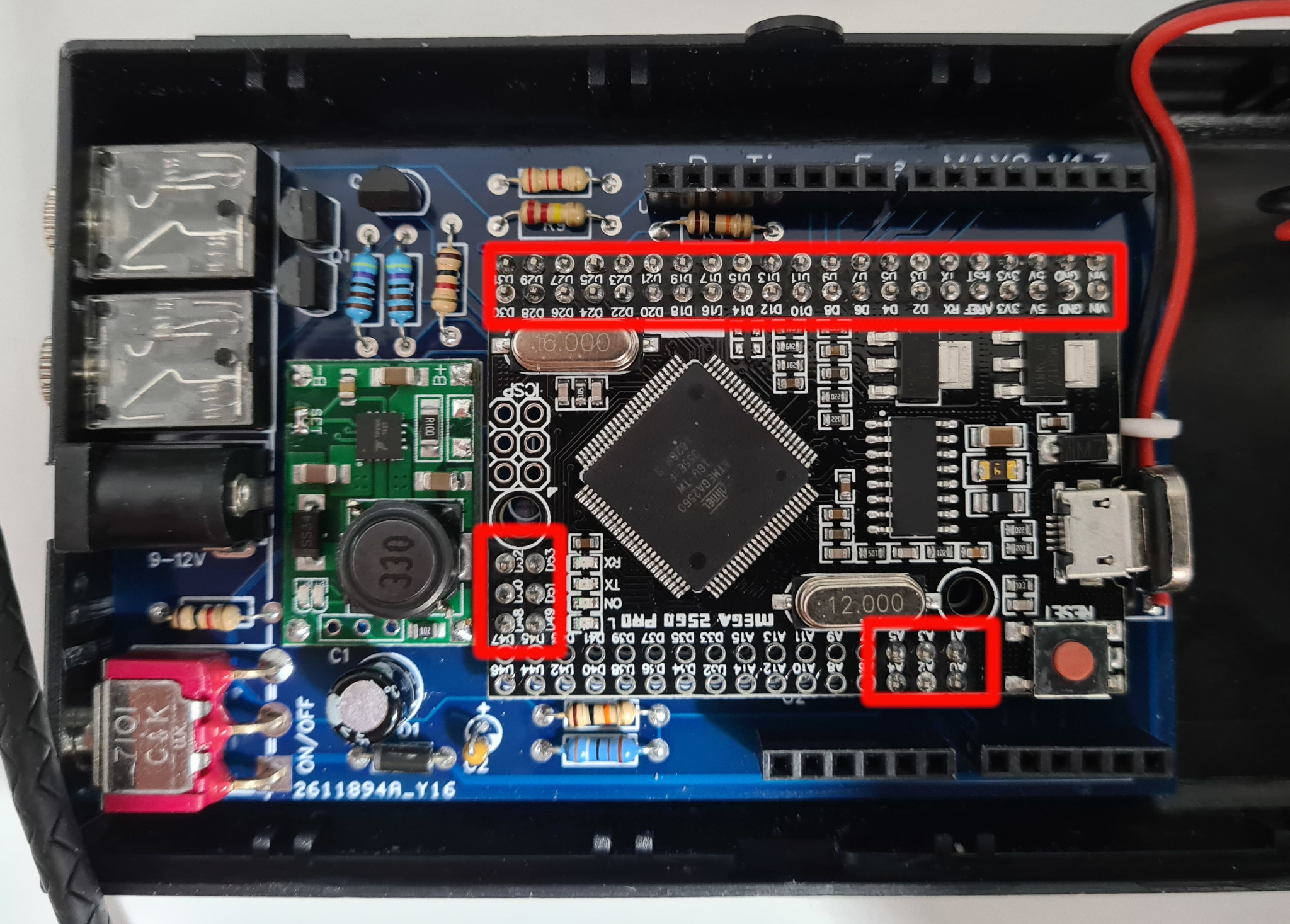
The next step would be to solder the 2-row male headers into the Arduino on the following location shown below
Solder the Arduino into the carrier board.
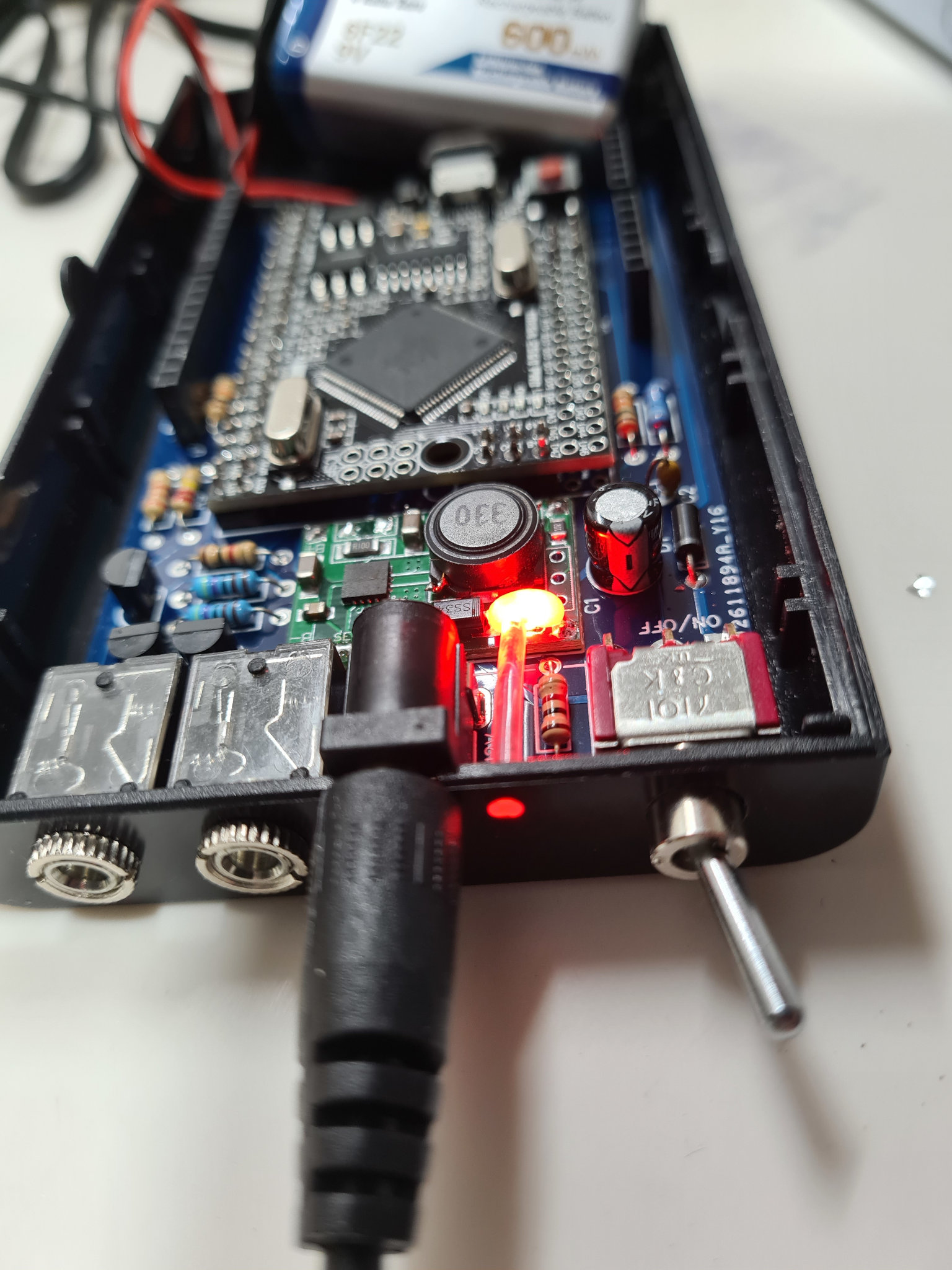
Install the fiber optic light guide and fix it over the TP5100 LEDs with a hot-melt glue as shown below.
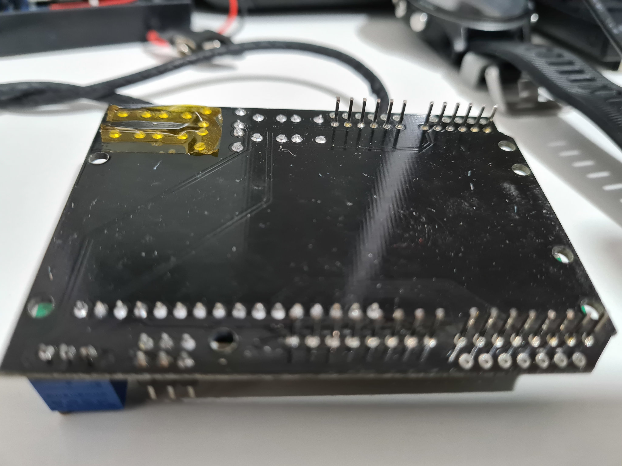
The LCD/button shield needs to be modified a bit as per instruction. This requires that the plastic in the headers on both sides be removed and the pins will need to be shortened by few millimeters so that it would mount flush in the carrier board via the female headers.
Trim the excess button wires and apply a small capton tape on the underside of the buttons this will prevent the buttons from shorting into the capacitor that is on the carrier board. What happens during my testing is that whenever I press a button the LCD backlight would turn off immediately.
Programming the firmware
If you’re using Windows you can use Xloader to upload the included firmware. For Linux I use avrdude.
Locate serial port
Plug your arduino to your computer and check the kernel message using dmesg look for something ‘ttyUSBx’
$ dmesg
[84192.594379] usb 1-1: new full-speed USB device number 5 using xhci_hcd
[84192.743985] usb 1-1: New USB device found, idVendor=1a86, idProduct=7523, bcdDevice= 2.54
[84192.743991] usb 1-1: New USB device strings: Mfr=0, Product=2, SerialNumber=0
[84192.743995] usb 1-1: Product: USB2.0-Serial
[84193.452284] usbcore: registered new interface driver usbserial_generic
[84193.452317] usbserial: USB Serial support registered for generic
[84193.459371] usbcore: registered new interface driver ch341
[84193.459975] usbserial: USB Serial support registered for ch341-uart
[84193.460653] ch341 1-1:1.0: ch341-uart converter detected
[84193.469498] usb 1-1: ch341-uart converter now attached to ttyUSB0
[84294.017798] usb 1-1: USB disconnect, device number 5
[84294.018263] ch341-uart ttyUSB0: ch341-uart converter now disconnected from ttyUSB0
[84294.018303] ch341 1-1:1.0: device disconnected
[84579.191795] usb 1-9: reset full-speed USB device number 4 using xhci_hcd
[85197.612929] usb 1-1: new full-speed USB device number 6 using xhci_hcd
[85197.762523] usb 1-1: New USB device found, idVendor=1a86, idProduct=7523, bcdDevice= 2.54
[85197.762530] usb 1-1: New USB device strings: Mfr=0, Product=2, SerialNumber=0
[85197.762534] usb 1-1: Product: USB2.0-Serial
[85197.764473] ch341 1-1:1.0: ch341-uart converter detected
[85197.765826] usb 1-1: ch341-uart converter now attached to ttyUSB0
Upload firmware to Arduino
sudo avrdude -p ATmega2560 -P /dev/ttyUSB0 -c wiring -U flash:w:LRTimelapse_Pro_Timer_MAX_LCD_V1_25.hex -D

avrdude: AVR device initialized and ready to accept instructions

Reading | ################################################## | 100% 0.01s

avrdude: Device signature = 0x1e9801 (probably m2560)
avrdude: reading input file "LRTimelapse_Pro_Timer_MAX_LCD_V1_25.hex"
avrdude: input file LRTimelapse_Pro_Timer_MAX_LCD_V1_25.hex auto detected as Intel Hex
avrdude: writing flash (47294 bytes):

Writing | ################################################## | 100% 7.33s

avrdude: 47294 bytes of flash written
avrdude: verifying flash memory against LRTimelapse_Pro_Timer_MAX_LCD_V1_25.hex:
avrdude: load data flash data from input file LRTimelapse_Pro_Timer_MAX_LCD_V1_25.hex:
avrdude: input file LRTimelapse_Pro_Timer_MAX_LCD_V1_25.hex auto detected as Intel Hex
avrdude: input file LRTimelapse_Pro_Timer_MAX_LCD_V1_25.hex contains 47294 bytes
avrdude: reading on-chip flash data:

Reading | ################################################## | 100% 5.65s

avrdude: verifying ...
avrdude: 47294 bytes of flash verified

avrdude: safemode: Fuses OK (E:FD, H:D8, L:FF)

avrdude done.  Thank you.
Turning on
Issues with the LCD button
One issue I encountered was that most of the buttons in my LCD were not working, it was because of some versions of the LCD shield output a different voltage from its voltage divider circuit. This is easily fixed by enabling and disabling some “define” statements in the source code . This will use the correct voltage readout for those versions of LCD.
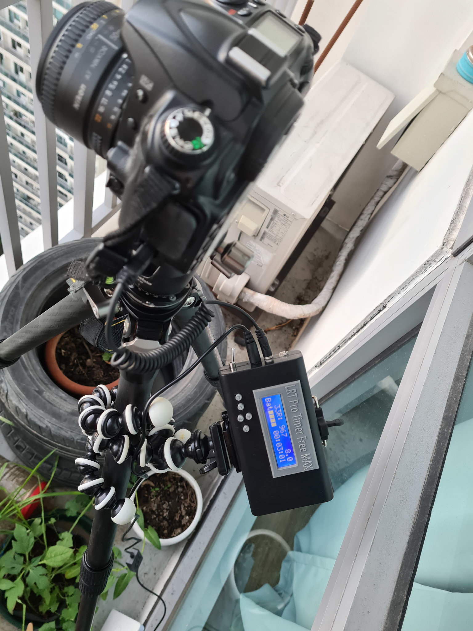
Timelapse demo
I did mess up the interval on this one, the interval was too short for shutter speed needed during the magic hour, I had to make changes in qDSLRDashboard w/c showed up as a sudden change in the speed of the clouds.
Updated firmware
As of this writing, I’ve already updated the firmware to v1.27 which Hans gladly provided to me when I discussed some issue running my version of LCD shield. It includes “Focus Stacking” improvement which I’m not currently using, if your primary usage is just Holy grail timelapse v1.25 would suffice. Just contact Hans to get the latest



No comment
Say something
Thank you
Your post has been submitted and will be published once it has been approved.
OK
OOPS!
Your post has not been submitted. Please return to the page and try again. Thank You!
If this error persists, please open an issue by clicking here.
OK